AURA Engineering Platform logo

Aerostatic bearing design · rotor-system engineering

Design the bearing. Configure the spindle. Verify the rotor.

AURA Engineering Platform is professional engineering software for direct calculation and inverse synthesis of aerostatic bearing systems. It connects journal, thrust, conical, adjustable-conical and combined supports to the drive unit, shaft, tool, load path and rotor-dynamic model.

Required performance → Bearing design → Drive Unit → Shaft → Tool → Supports → Critical speeds and response → Evidence status → Decision boundary.

Hardware-grounded methodology

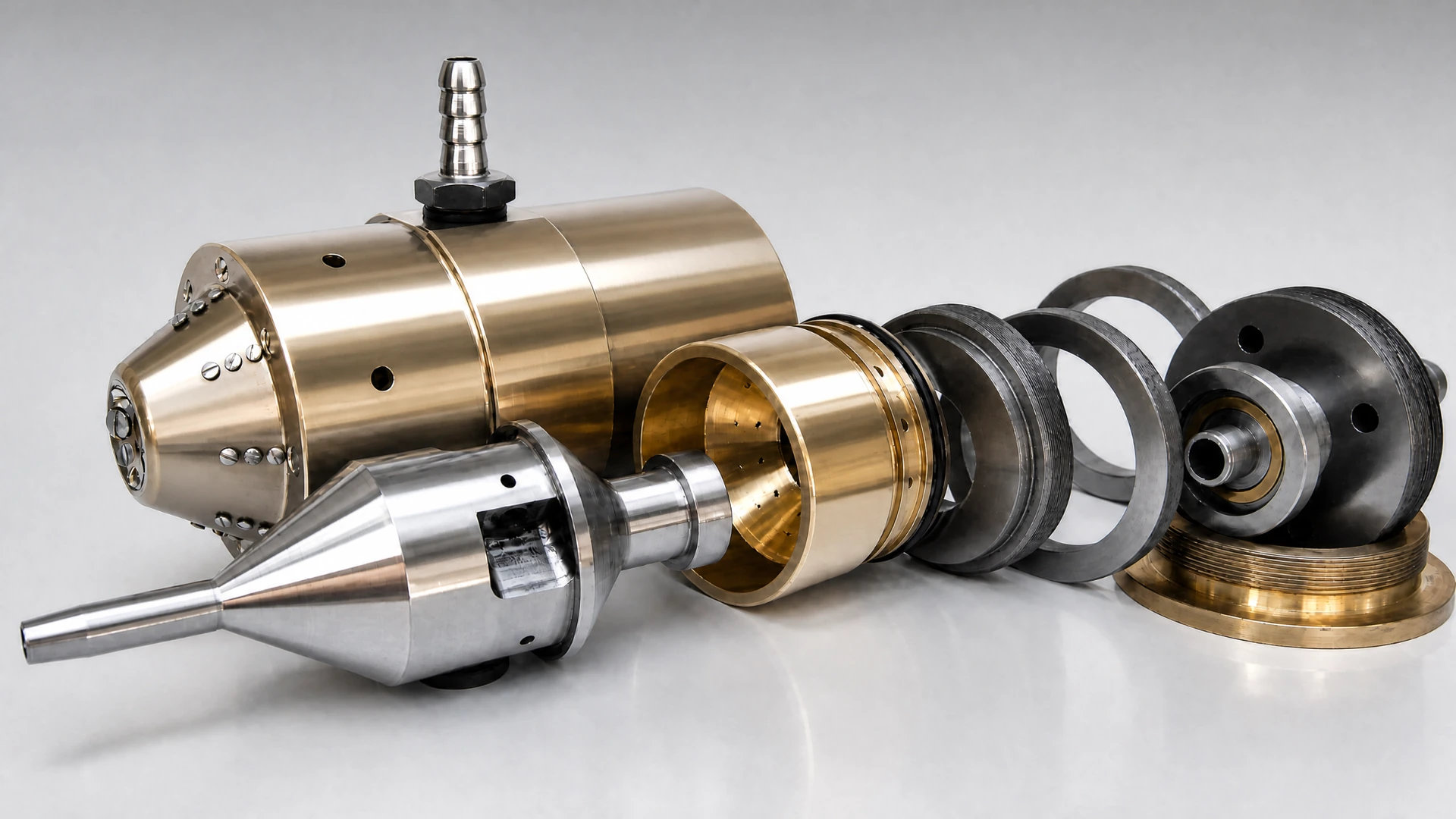
AURA is calculation-first, but not calculation-only. Its engineering methods are grounded in theory → FEM comparison → experiment → manufactured aerostatic-bearing hardware, including a conical gas-static spindle development track.

Current access: expert-assisted AURA engineering pilots. Fixed-scope evidence reviews remain available as a separate Breshev Engineering service.

2 public anchors
Two public engineering-evidence anchors committed in the registry.
10.282% max residual
Journal L4 dual benchmark-family holdout, 4/4 holdout rows closed.
10 Level A checks
Solver-sanity anchors at machine precision in the active regression foundation.
Direct bearing calculation Inverse parameter synthesis Journal · thrust · conical supports Air-bearing spindle layout Critical speed + unbalance response Balancing evidence Release decision boundaries

What AURA is

A professional engineering suite for aerostatic and gas-static bearing systems, high-speed spindles, precision rotors, microturbomachinery, and adjacent non-contact rotating systems. Its core is bearing calculation, synthesis and configuration; dynamics and evidence extend that core to the complete machine decision.

Where it comes from

A research lineage in aerostatic and gas-static bearing engineering spanning decades, carried through theory, FEM, experiment, and manufactured hardware — including conical gas-static support development. AURA formalizes that discipline into a workflow.

What AURA is not

AURA is not a general-purpose CAE replacement, and it is not only a validation layer. It is a specialist bearing-and-rotor engineering platform that can exchange evidence with broader CAD, CAE, metrology and test workflows.

Current product status

Current pilots are expert-assisted engineering engagements powered by the AURA workflow. AURA is not yet a self-serve SaaS.

Release evidence, not just coefficients

Most tools give coefficients. AURA tells you what those coefficients are allowed to prove after geometry, clearance, thermal state, balance process, rotor dynamics, validation scope, and decision limits are considered.

Open evidence surface

Registry anchors, residuals, applicability boundaries, technical notes, DOI records, and explicit claim boundaries remain public and inspectable.

Closed engineering engine

The solver implementation, perturbation-method core, coefficient engine, damping logic, and decision heuristics remain protected.

Hardware-grounded methodology

Built against the theory-to-hardware gap, not around it.

Practical gas-bearing work is not won by clean calculator output. Surface finish, geometry, clearance, manufacturing process, and system-level behaviour can dominate the final result. AURA is built from that reality: the workflow is designed to keep assumptions, coefficient evidence, dynamic screening, and claim boundaries visible before a result is trusted.

Theory that has not earned its trust is just a guess with decimal places. AURA formalizes the discipline that connects theory, FEM, experiment, manufactured hardware, and decision limits.

Conical gas-static support track

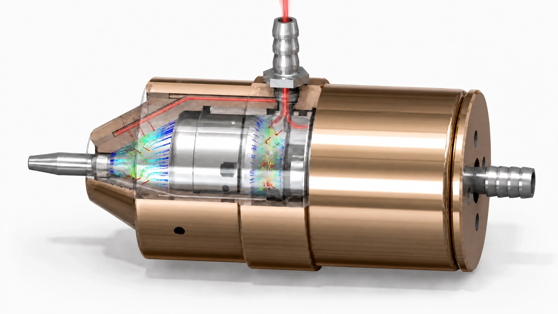
One internal credibility anchor behind the methodology is a spindle built around conical aerostatic supports — an uncommon, high-sensitivity configuration where the calculation-to-hardware loop is difficult to hide behind generic assumptions.

This does not mean every AURA output is a production-release claim. It means the platform is built from hardware-aware engineering discipline rather than calculator-only confidence.

Theory and FEM comparison

Analytical and perturbation-method calculations are treated as engineering evidence only when their assumptions and comparison basis are visible.

Experiment and manufactured parts

AURA's positioning explicitly respects the make-and-test loop: real geometry, surface finish, clearances, and manufacturing process can change performance.

Claim-bounded decisions

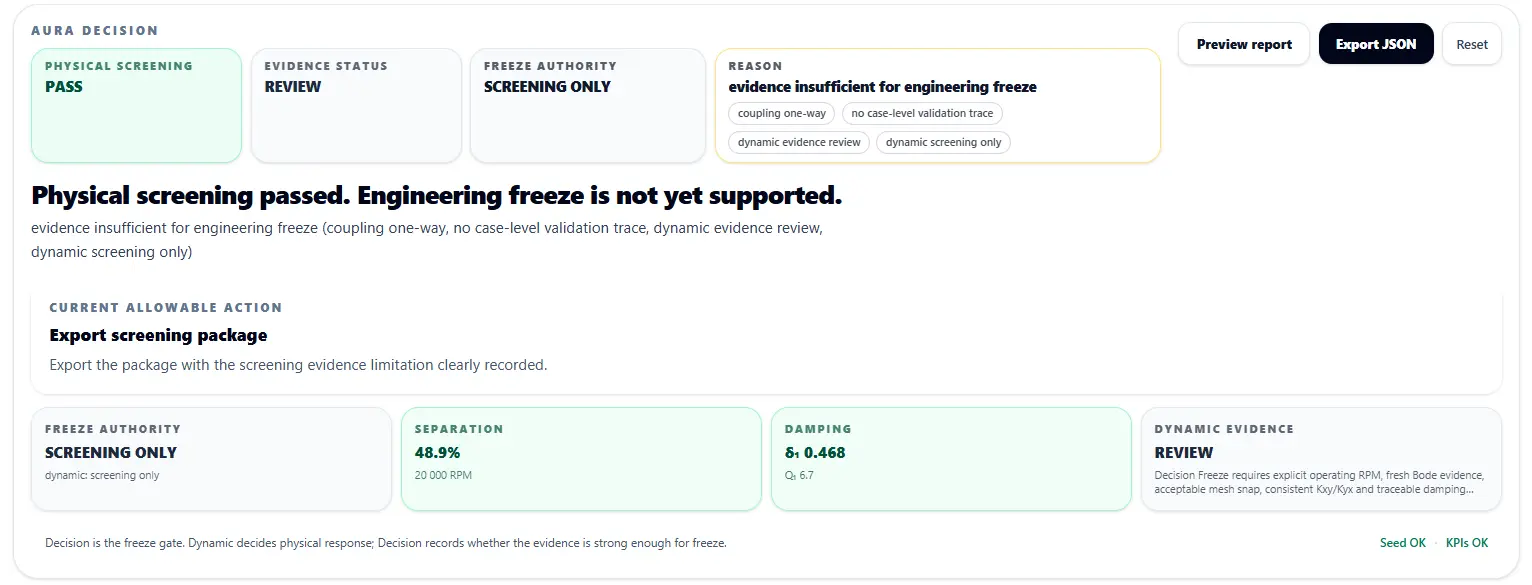
The workflow separates a clean calculation from a defensible result. PASS can still remain SCREENING ONLY until evidence maturity supports release.

Theorygas-film equations and perturbation method
FEMcomparison against numerical reference paths
Experimentmeasurement-informed correction and validation
Hardwaremanufactured aerostatic-bearing spindle work

AURA Preview · controlled product proof

From application fit to defensible gas-bearing rotor decisions.

AURA Preview is a locked, representative workflow demonstration. It shows how a gas-static rotor support decision moves from application fit and support architecture to bearing parameter synthesis, coefficient evidence, rotor-dynamic screening, and a claim-bounded decision.

locked representative case not a public solver no production validation claim

Why this preview exists

AURA is not being exposed as a self-serve calculator. The preview communicates the product category: application fit → support synthesis → coefficient evidence → rotor dynamics → decision / freeze.

Full access

Full AURA workflows remain private and expert-assisted through scoped pilot projects.

The AURA Decision Stack

Nine steps from application fit to freeze authority

The market decision starts before bearing geometry is selected: should this application use non-contact gas-static support at all? Then the workflow carries evidence forward into synthesis, dynamics, and decision authority.

0
Bearing technology fit

Is non-contact gas-static support justified by the application?

1
Machine type

Spindle, wafer-inspection rotor, microturbomachinery shaft, or adjacent precision rotor.

2
Loads

External loads, moments, overhang, speed, support reactions, and uncertainty ranges.

3
Architecture

Journal, thrust, conical, hybrid, radial / axial support topology.

4
Layout

Drive unit → shaft → tool, support placement, rotor span, and load path.

5
Bearing parameter synthesis

Radius, length, clearance, supply pressure, restrictors, rows, and feed-zone layout.

6
Coefficient evidence

Load, stiffness, damping, cross-coupling, and flow with method provenance.

7
Rotor-dynamic screening

Critical-speed separation, Campbell behaviour, response, stability, and clearance margin.

8
Decision / freeze

PASS, REVIEW, Screening Freeze, Engineering-Freeze candidate, and claim boundary.

Locked preview case

Wafer inspection spindle · representative screening case

The case is fixed and illustrative. It demonstrates workflow traceability, not arbitrary geometry optimization or production validation. The numerical values are kept conservative in claim scope and should be treated as representative screening evidence.

Application & layout

Application fitNon-contact support plausible for repeatability, low friction, clean operation, and low wear
Machine typePrecision spindle / wafer-inspection rotor
Operating speed20,000 rpm
Layout chainDU → shaft → tool

Bearing candidate

Support typeGas-static journal support
Journal radius R35 mm
Bearing length L50 mm
Clearance C15 µm
Supply pressure pₛ6 bar

Coefficient evidence

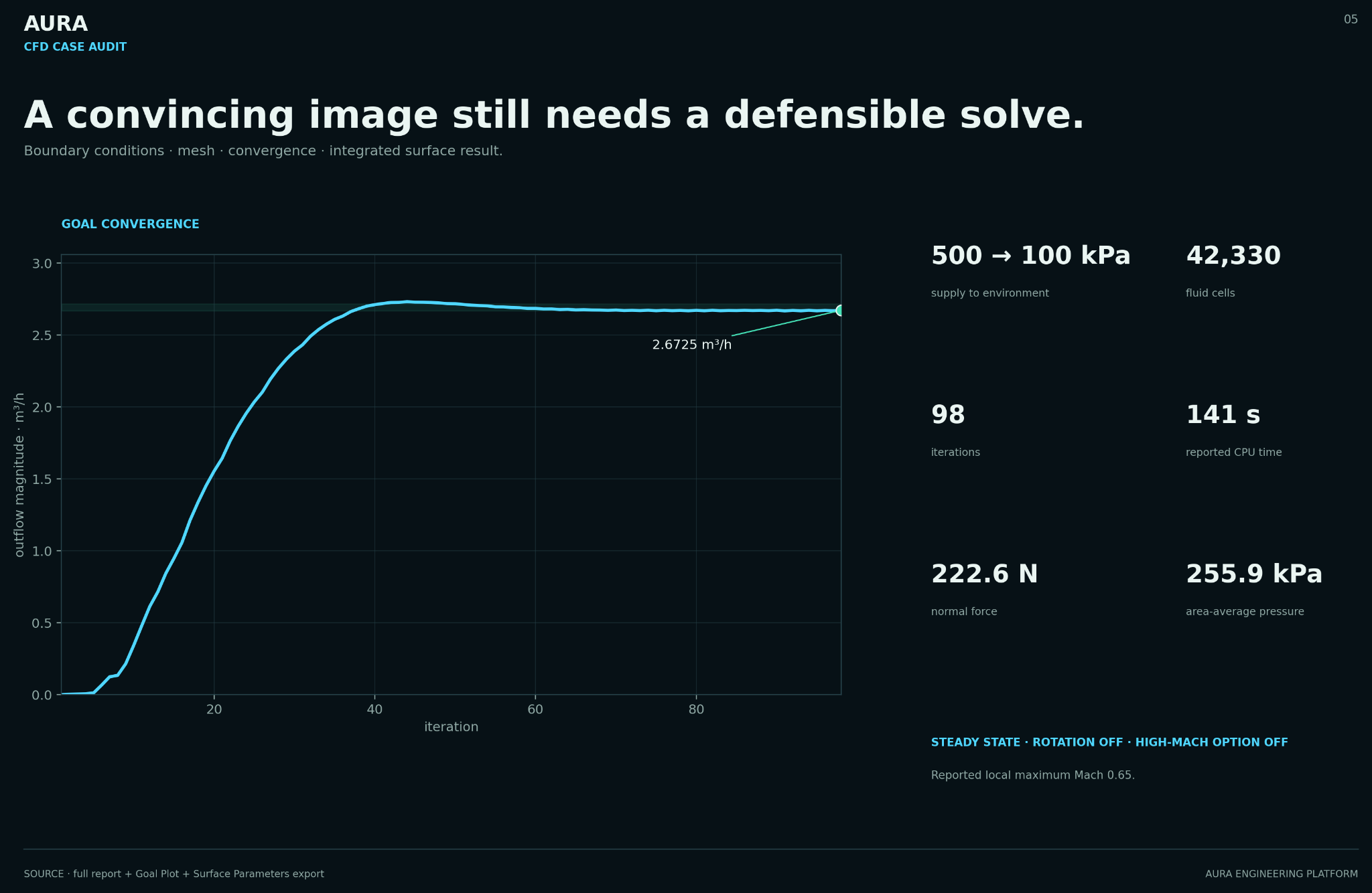
Load capacity195.9 N
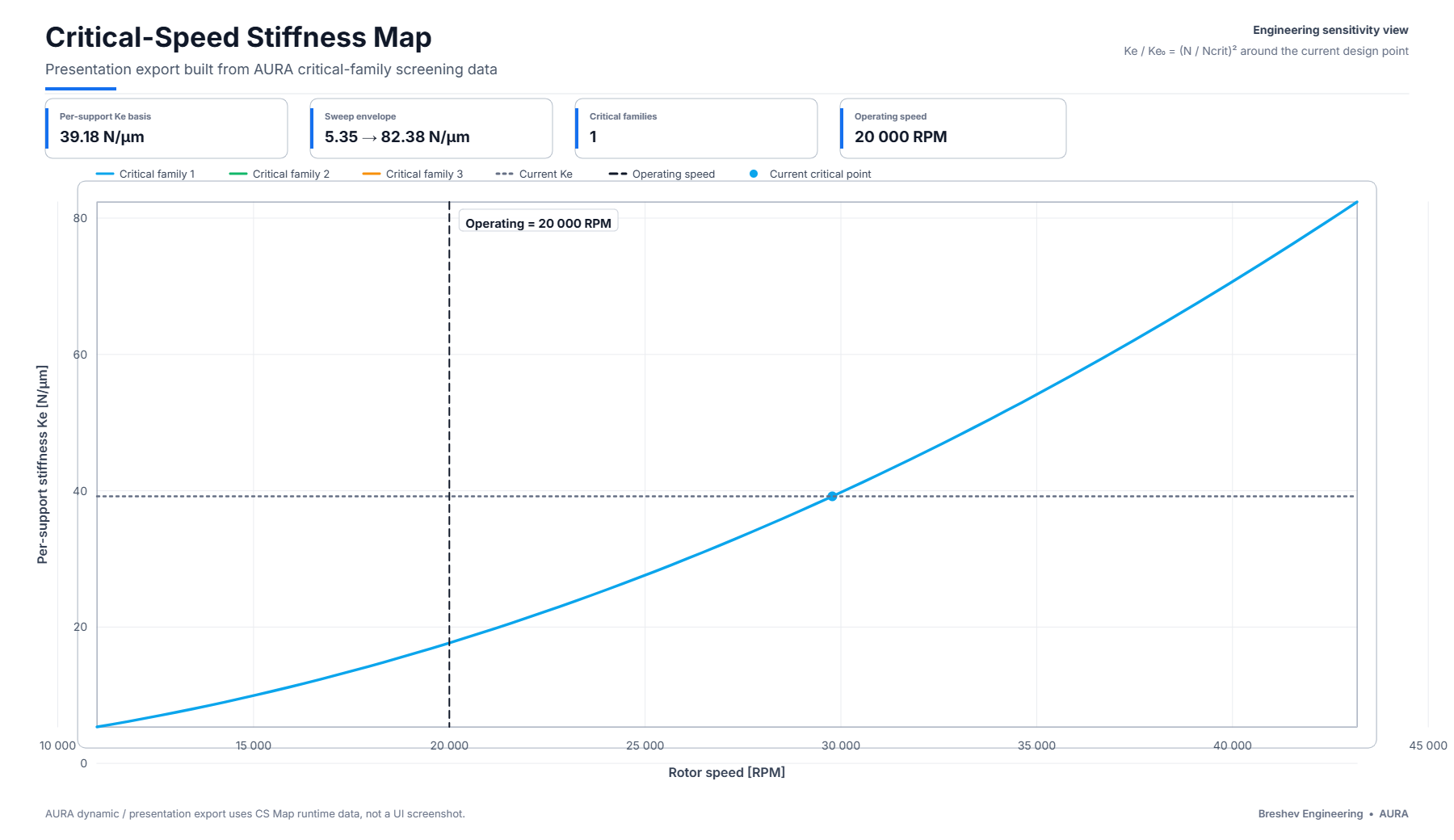
Stiffness Kxx39.18 N/µm
Cross-coupling magnitude10.258 N/µm
Flow1.92 m³/h
Damping levelscreening-level provenance

Dynamic screening

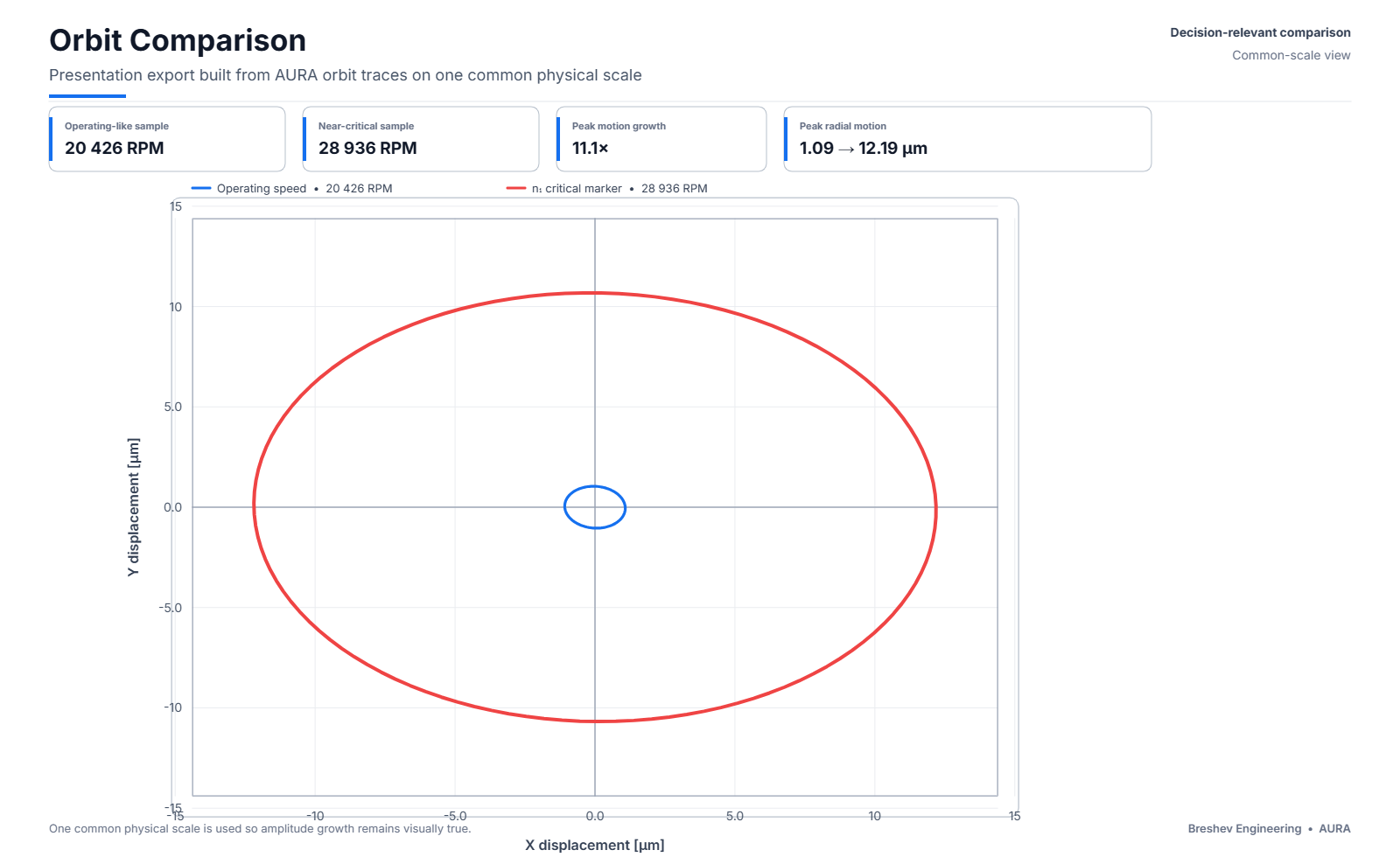
Whirl screening estimate~32,700 rpm · >60% above operation
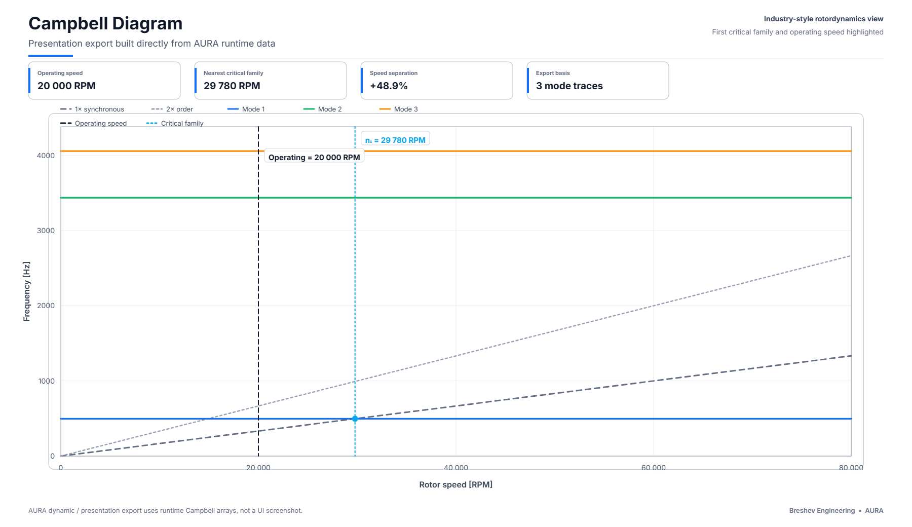
Campbell marker~29,779 rpm · ~49% above operation
Couplingone-way bearing → rotor handoff
Benchmark tracenot attached to this preview case

Decision

CALCULATION PASS FREEZE: SCREENING ONLY

Damping provenance, coupling maturity, benchmark trace, and validation scope are not sufficient for engineering freeze. This is not a failure of the candidate; it is a claim boundary.

This preview demonstrates workflow traceability and decision discipline. It does not provide final bearing release, production qualification, or access to AURA solver internals.

What this preview demonstrates

  • Application-fit framing before bearing selection
  • Requirement-to-support workflow structure
  • Coefficient provenance concept
  • Rotor-dynamic screening handoff
  • Separation of calculation pass from freeze authority

What this preview does not claim

  • Final bearing design release
  • Arbitrary geometry optimization
  • Full CFD or experimental validation
  • Production qualification
  • Replacement for scoped engineering review

Workflow demo

A short walkthrough of the AURA workflow: bearing calculation and configuration → rotor-dynamic screening → evidence status → decision boundary.

2-minute product walkthrough
Scope note: benchmark-scope demonstration. Not a universal production validation claim.
Demo transcript summary: AURA calculates the gas-static support, connects its coefficients to the rotor model, evaluates the dynamic response, and separates a calculation result from release authority.
Bearing coefficients Gas-film outputs are treated as coefficient evidence, then exported into the Dynamic workspace.
Rotor-dynamic screening Support data enters a rotor model for critical-speed behavior, response, and stability screening.
Decision gate The calculation verdict is separated from freeze authority, with limitations recorded explicitly.
Public validation layer Registry release, Zenodo DOI, public anchors, residuals, and leakage-audit status are visible inside AURA.

One engineering chain, five connected layers

AURA begins with the bearing calculation and ends at the release boundary. Direct analysis, inverse synthesis, machine configuration, rotor dynamics and evidence authority use the same configuration state instead of separate spreadsheets and disconnected model snapshots.

1 · Calculation Core

Direct calculation and inverse parameter synthesis for journal, thrust, conical, adjustable-conical and combined gas-static supports. Outputs include load capacity, flow, stiffness, damping, cross-coupling and operating state.

2 · Configuration Workflow

Drive Unit → Shaft → Tool → Supports. AURA records support placement, rotor span, overhang, reactions and the load path that the bearing and rotor models must represent.

3 · Rotor Dynamics

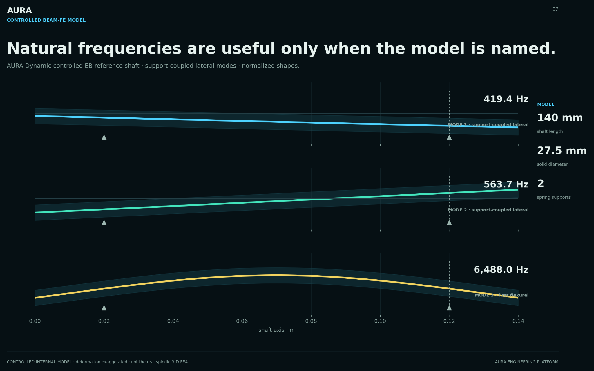
Critical speeds, Campbell behaviour, unbalance response, Bode traces, orbit, damping and stability indicators are evaluated from the connected support state.

4 · Evidence Layer

Coefficient provenance, geometry and clearance state, validation trace, balancing, assembly evidence and the operating envelope remain attached to the result.

5 · Decision Layer

PASS, REVIEW, SCREENING ONLY, TEST REQUIRED and HOLD state what the current engineering evidence can support and what must happen next.

AURA workflow object map application fit → freeze boundary
0

Application fit

Non-contact support decision before bearing geometry is selected.

1–2

Machine + loads

Machine type, speed range, forces, moments, overhang, and support reactions.

3–4

Architecture + layout

Support topology, DU → shaft → tool chain, rotor span, and load path.

5

Bearing synthesis

Radius, length, clearance, pressure, restrictors, rows, and feed-zone layout.

↓ coefficient evidence handoff
6

Coefficient evidence

Load, stiffness, damping, cross-coupling, flow, confidence level, and provenance.

7

Rotor-dynamic screening

Critical-speed separation, Campbell behavior, Bode/orbit response, and stability flags.

8

Decision / freeze

Calculation PASS can still remain SCREENING ONLY if evidence is not release-grade.

Trust

Registry layer

Public anchors, residuals, lifecycle state, DOI, and applicability boundary.

Inputrequirements + layout
Synthesisbearing candidate
K/C/Qcoefficient evidence
Dynamicscreening traces
Decisionclaim boundary
Public surface: the site shows the workflow structure without depending on unavailable screenshot files or exposing the full solver. Full AURA remains controlled for scoped pilot work.

Typical output

  • Direct bearing calculation or constraint-driven synthesis result
  • Load capacity, flow, stiffness, damping and cross-coupled coefficients
  • Drive, shaft, tool, support and reaction configuration
  • Campbell, Bode, orbit, and stability traces for rotor-dynamic screening
  • Decision summary with PASS / REVIEW / SCREENING ONLY / TEST REQUIRED / HOLD rationale
  • Validation provenance linked to public registry anchors
  • Explicit limitations and applicability boundaries
  • Reusable input template for follow-on cases in the same architecture class

Workflow principle: calculate the support, configure the machine, analyse the rotor, then state what the connected result is ready to prove.

Open Validation Registry

AURA is backed by a public evidence-gated registry. The registry exposes specific anchors, residuals, lifecycle states, and applicability boundaries instead of relying on asserted validation language.

2 public engineering-evidence anchors
3.938% / 7.143% / 7.692%
Conical aerostatic method-chain residuals.
4/4 holdout rows
Journal L4 dual benchmark-family holdout closed.
PASS leakage audit
Calibration and holdout row IDs are disjoint.

Anchor 1 — Conical aerostatic bearing

VCR_BRESHEV_CONICAL_P05_METHOD_CHAIN_001

Method-chain validation for a conical aerostatic bearing configuration: experimental measurement → FEM reference → AURA Perturbation Method.

Anchor 2 — Journal aerostatic bearing

VCR_AURA_JOURNAL_AEROSTATIC_L4_DUAL_BENCHMARK_001

Dynamic stiffness and damping coefficient identification validated against Kozánek 2009 and Fleming/NASA TN D-8270 holdout families.

This is not an arbitrary-geometry production release claim. It is benchmark-scope engineering confidence for documented benchmark families and scoped bearing-family evidence.

Technical notes

Short engineering notes that explain the AURA decision logic in public, without exposing the full solver.

Technical Note 01 — Static PASS is not Engineering Freeze

A gas-bearing support can pass load, stiffness, and clearance checks while still remaining screening-only once damping provenance, cross-coupling, rotor-bearing coupling, and benchmark trace are considered.

Technical Note 02 — From Application Fit to Gas-Bearing Support Architecture

Before bearing radius, clearance, or supply pressure are selected, the real decision is whether non-contact gas-static support is justified by the application — and what support architecture can carry the machine requirements.

Technical Note 03 — Geometry, Clearance, and Balance Are the First Validation Gates

A coefficient is not release evidence unless the manufactured geometry, clearance state, balance process, and vibration/orbit criteria behind it are known.

Technical Note 04 — Residual Imbalance Is Not Release Evidence

High-speed precision rotors need a balancing evidence trail: rotor regime, grade rationale, correction path, assembly state, balance-error sources, and vibration response.

Technical Note 05 — Release Evidence Has an Operating Envelope

A factory release decision remains authoritative only inside the speed, load, thermal, ambient, mounting, control, and duty-cycle envelope that produced its evidence.

A balancing result is not plane-free.

A residual-unbalance value becomes release evidence only when the tolerance planes, correction and measurement planes, machine/process capability, rotor-state repeatability, assembly state, and service-relevant speed path are preserved with it. A single U / U-limit ratio cannot carry that decision by itself.

Tolerance planes ≠ correction planes

The evidence record needs the permissible total, its allocation, the relevant plane coordinates, and the transformation used to judge the measured state in the tolerance planes.

Calibration ≠ demonstrated capability

Task-specific evidence includes minimum achievable residual unbalance, reduction ratio, plane separation, angular capability, correction resolution, and setup applicability.

Residual value ≠ release authority

Vector repeatability, assembly transfer, modal sensitivity, damping provenance, and the complete acceleration/deceleration path bound what the result is allowed to prove.

Balancing Evidence Review

A fixed-scope, one-week engineering review of the balancing evidence behind one high-speed rotor: tolerance-plane allocation, correction-plane mapping, grade rationale, machine/process capability, vector repeatability, assembly transfer, modal sensitivity, operating envelope, and what the residual imbalance number is actually allowed to prove.

One rotor · one week · €1,900 fixed

The output is a written evidence map and an explicit release-boundary statement. This is not a recalculation service and not a replacement for a balancing shop; it makes the evidence behind the existing balancing result reviewable.

Use-case pages

AURA is being expanded from a single landing page into a focused technical site. These pages describe where the workflow fits and what decision risks it exposes.

Precision spindles

Workflow for spindle gas-bearing decisions: support architecture, coefficient evidence, rotor-dynamic screening, and freeze boundary.

Semiconductor positioning

Application-fit framing for clean, low-friction, high-repeatability non-contact support systems.

Cryogenic turboexpanders

Scoped screening logic for high-speed gas-bearing rotor systems where coefficient provenance and dynamics matter.

Paid pilot model

AURA starts with a scoped paid pilot: a short expert-assisted engagement to test fit on a real architecture and produce a decision-ready package.

Pilot scope

  • Duration: typically 2–4 weeks
  • Investment anchor: typically €12K–€40K depending on scope and data readiness
  • Fixed-fee where appropriate, with mutual success criteria
  • Output: decision report, reusable input template, validation provenance package

Success criteria

  • Clear feasibility verdict delivered
  • Repeatable input template delivered
  • Internal review pack quality sufficient for engineering leadership
  • Explicit remediation discussion if criteria are not met

Continuity and delivery

Pilot delivery is remote-first. Inputs, assumptions, intermediate files, and final reports are versioned and backed up. If a force-majeure disruption affects schedule, the engagement pauses with the current evidence state preserved; delivery resumes or is re-scoped by written agreement.

Fit and scope

Good fit

  • Aerostatic / gas-static journal, thrust, conical, or related bearing configurations
  • Precision spindles, microturbomachinery, cryogenic turboexpanders, semiconductor positioning systems
  • Pre-CAE sizing, architecture screening, qualification documentation, validation provenance
  • Teams already using ANSYS / MSC Adams / SolidWorks / similar CAE tools

Not a fit

  • Hydrodynamic-only bearing systems
  • Magnetic bearings as the primary bearing physics
  • General-purpose CAE replacement
  • Post-design qualification after the architecture is already frozen

Who is behind AURA

Oleksii Breshev

Founder, lead developer, and technical architect. Mechanical engineering PhD; senior doctorate currently in progress at National University “Kyiv Aviation Institute”. Builds the AURA platform and conducts customer engineering work directly.

V. Breshev

Chief scientist and methodology co-author. 30+ years of original aerostatic bearing research and originator of the perturbation-method core used in AURA.

Two-generation engineering depth

The platform is built on continuity of work in the same physics specialty: analytical methods, CFD comparison, experimental evidence, and practical engineering judgment across many bearing cases.

FAQ

Is AURA only an air-bearing calculator?

No. Direct aerostatic-bearing calculation is part of the core, together with inverse parameter synthesis. AURA then connects the support result to the drive, shaft and tool layout, rotor-dynamic analysis, validation evidence and the release-decision boundary. The public website shows a controlled preview; current full workflows are expert-assisted.

Does AURA replace prototype testing?

No. AURA is designed to structure the pre-prototype and review workflow: assumptions, support synthesis, coefficient evidence, rotor-dynamic screening, and claim boundaries. Prototype measurement remains essential when manufacturing-sensitive variables such as clearance, surface finish, and geometry dominate performance.

What decision does AURA support?

AURA supports bearing sizing and synthesis, support-architecture comparison, high-speed spindle and rotor-system configuration, critical-speed and response screening, and evidence-controlled release decisions for gas-static bearing systems.

Does a calculation PASS mean engineering freeze?

No. A calculation can pass while freeze remains screening-only if damping provenance, coupling maturity, benchmark trace, tolerance basis, or validation scope are not sufficient for release.

What is the best first pilot case?

The best first case has a defined machine type, RPM range, support architecture, load or stiffness target, available geometry constraints, and a clear decision question.

Contact

Oleksii Breshev — Founder, AURA Engineering Platform

Email: aura@breshevengineering.com

  • Best first message: machine type + RPM range + constraints
  • For technical review: include architecture class and available validation data

Next step: we confirm fit in a short call and share a one-page pilot scope when the case is appropriate.